


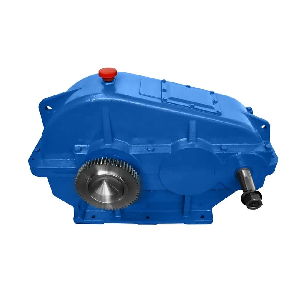
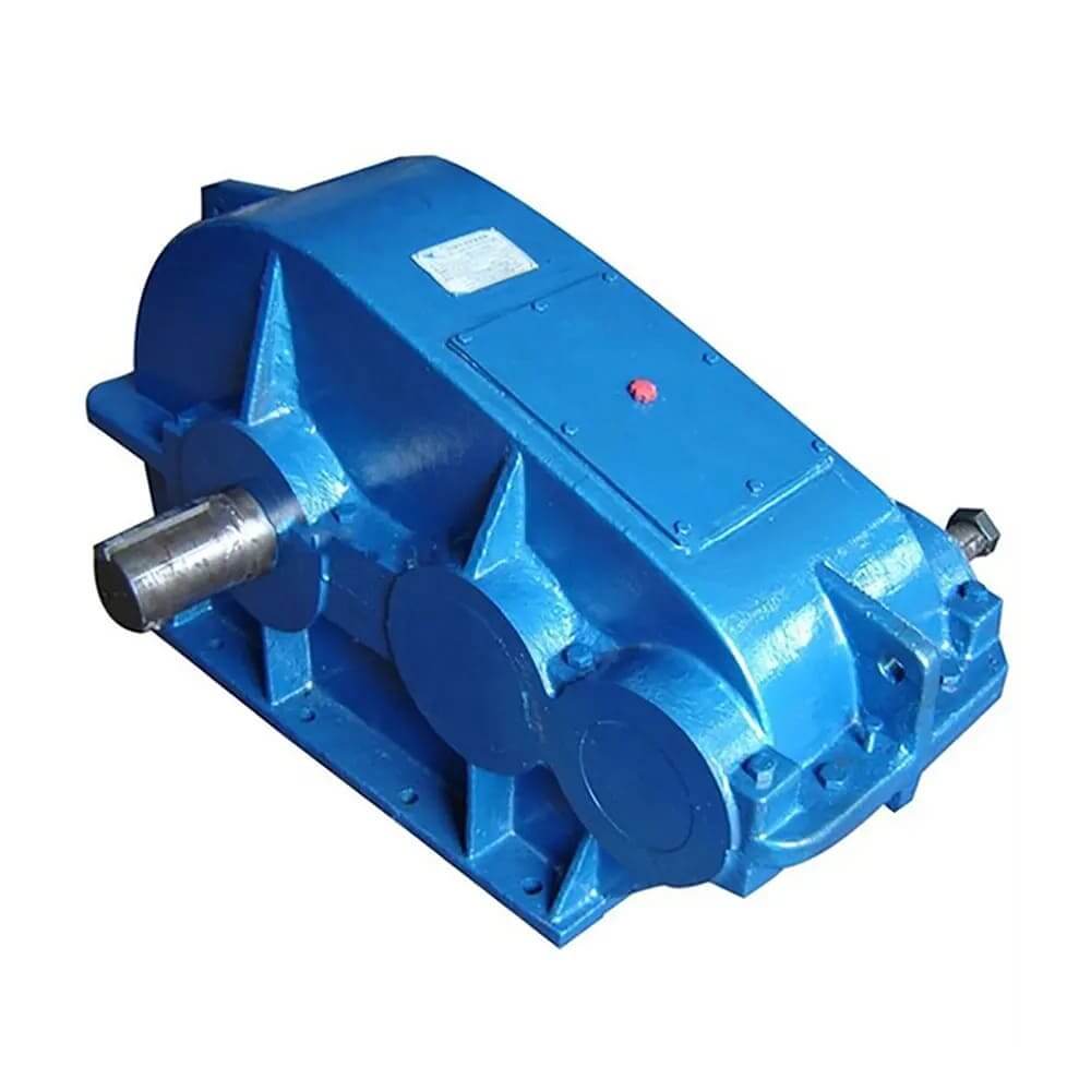
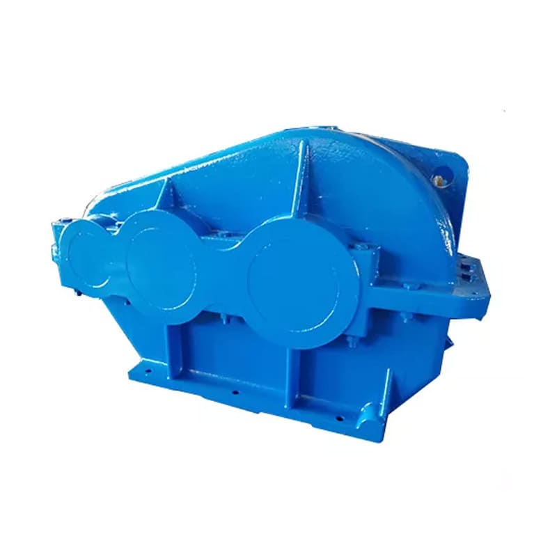


JZQ/ZQ/ZQA/ZQH Series Cylindrical Gear Reducer
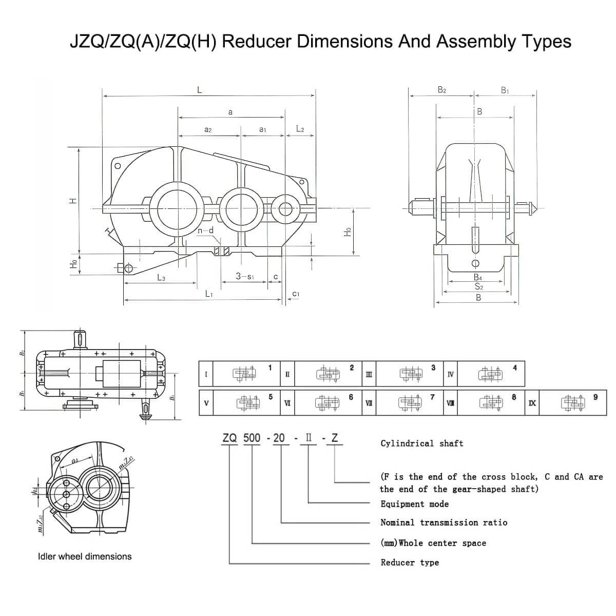
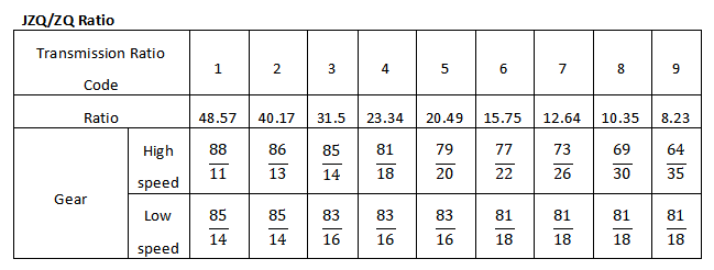
【Standard Ratios】 8.23, 10.35, 12.64, 15.75, 20.49, 23.34, 31.5, 40.17, 48.57
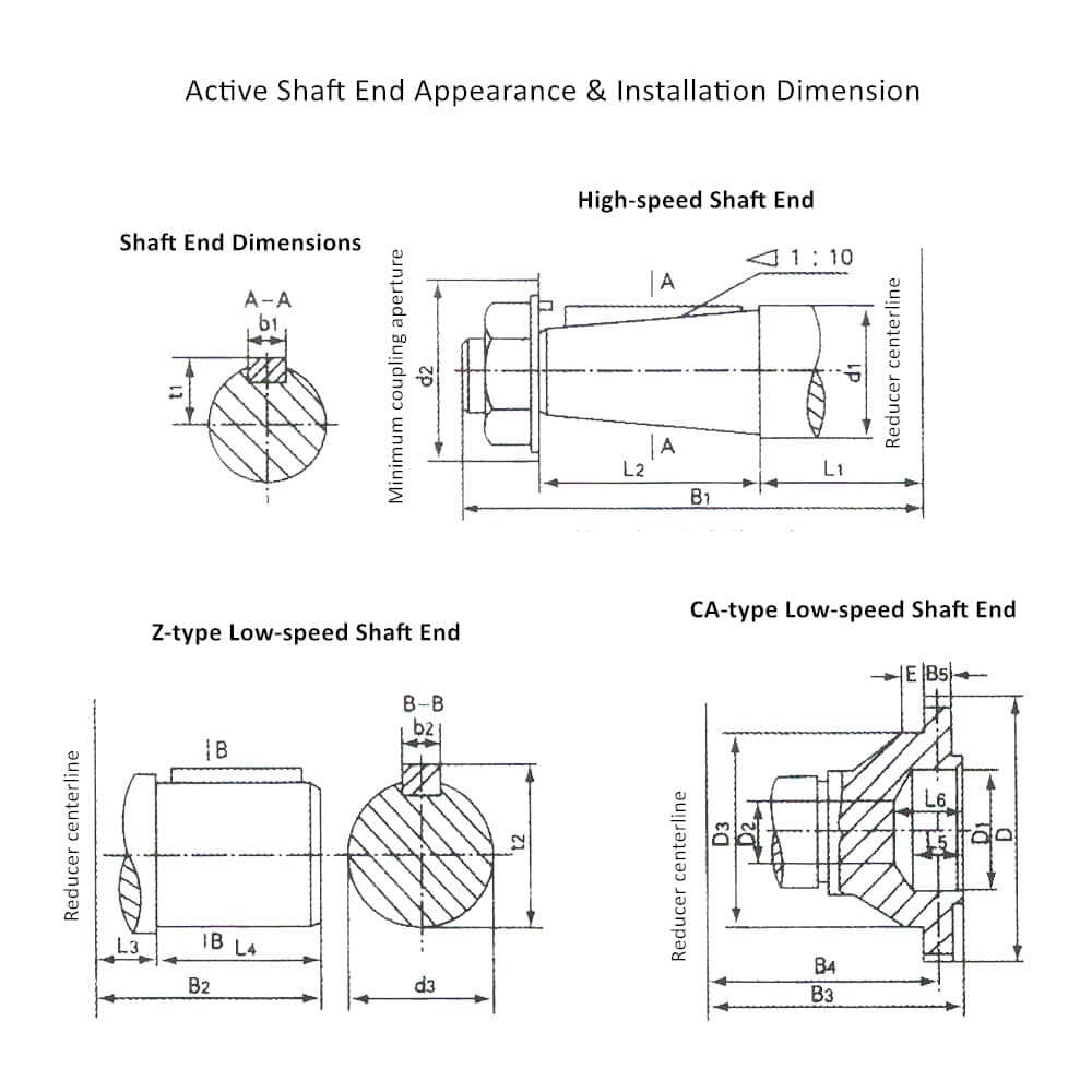
【Mounting Configurations】 9 assembly types (I-IX) with 3 output shaft types: Z-type: Cylindrical shaft end; C/CA-type: Gear-type shaft end; F-type: Cross coupling shaft end
【Temperature Range】 -40℃ to +40℃ operation
【Efficacité】 ≥94% with involute tooth profile
 Chat en ligne sur WhatsApp
Avantages
Les JZQ/ZQ /ZQA/ZQH series cylindrical gear reducer, également appelé cylindrical gearbox, cylindrical speed reducer, or cylindrical reducer. They are widely used in heavy industries such as mining, metallurgy, cement, and material handling. These reducers are designed for high torque, strong load capacity, and long service life, making them suitable for various industrial applications.
Principal Features
- High transmission rate: single-level greater than 96.5%, dual-level greater than 93%, third-level greater than 90%.
- Stable operation and low noise.
- Small size, light weight, long service life, and high carrying capacity.
- Easy to disassemble and install.
- The structure adopts the vertical installation.
- The high-speed shaft speed does not exceed 1500 rpm, the gear circumferential speed is not more than 12 m/s, the efficiency is not less than 0.94, the working environment is -40℃ to +40℃, and it can run in both forward and reverse rotation.
ZQ reducer is divided into 8 types according to the center distance: 250, 350, 400, 500, 650, 750, 850, 1000.
ZQ cylindrical gear reducer has become a classic choice in the field of traditional industrial transmission due to its economy, durability, and wide applicability, especially suitable for cost-sensitive and moderate load occasions. If you need higher load capacity or harsh working conditions (such as high temperature or heavy load), you can consider upgrading to a DCY hardened gear reducer or ZSY medium hardened gear series.


Structure du produit
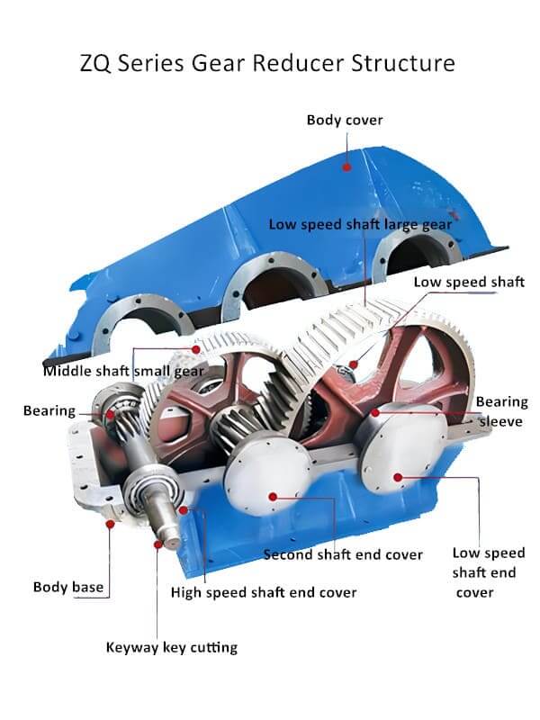
【JZQ/ZQ/ZQA/ZQH series cylindrical gear reducer Structure】
JZQ/ZQ/ZQA/ZQH series cylindrical gear reducer is mainly composed of gears, bearings, housing, and other components.
- Gear: The reducer contains multi-stage cylindrical gears, which realize power transmission and deceleration through precise meshing.
- Bearing: Support the rotation of the gears to reduce friction and wear.
- Housing: Protect the internal mechanical parts and provide necessary lubrication and cooling.
- The input shaft and output shaft: Connect the power source and load respectively to realize power input and output.
- Coupling: Used to connect the input shaft and the power source. Common ones include cylindrical shaft extension (Z type), gear shaft extension (CA type) and Euler coupling type (F type).
【JZQ/ZQ/ZQA/ZQH series cylindrical gear reducer Working principle】
The reducer realizes power deceleration and torque increase through the precise meshing of two-stage cylindrical gears. The efficient gear transmission design ensures low loss and high efficiency during energy conversion. The transmission ratio has a wide range of options, such as 48.57, 40.17, 31.5, etc., to meet different transmission needs.
Paramètres techniques
Overview of ZQ Cylindrical Gear Reducer
| Gear Reducer Serials | Design | Caractéristiques | Typical Industrial Applications |
| JZQ(Basie Type) | Early model, simpler structureet moderate load capacity. | 1. Standard parallel shaft cylindrical gear design.
2. Suitable for stable, low-impact machinery. 3. Limites: Gradually being replaced by ZQ & ZQ(A) due to lower durability. |
|
| ZQ(Standard Type) | Evolved from JZQ, with improved gear materials and strength. | 1. Higher torque capacity et longer lifespan than JZQ.
2. Used in medium-load, continuous operation applications. |
|
| ZQ(A )(Enhanced Type) | Upgraded version of ZQ, featuring better bearings, hardened gears, and reinforced housing. | 1. Higher impact resistance than standard ZQ.
2. Suitable for heavier loads, dust, and moisture exposure (e.g., mining & bulk material handling). |
|
| ZQ(H) (Heavy-Duty Type) | High-strength alloy steel gears, reinforced shaft supports, and thick-walled housing. |
|
|
Appearance and installation dimensions
| Modèle | ZQ250 | ZQ350 | ZQ400 | ZQ500 | ZQ650 | ZQ750 | ZQ850 | ZQ1000 | ||
| Center Distance(mm) | A | 250 | 350 | 400 | 500 | 650 | 750 | 850 | 1000 | |
| a1 | 100 | 150 | 150 | 200 | 250 | 300 | 350 | 400 | ||
| a2 | 150 | 200 | 250 | 300 | 400 | 450 | 500 | 600 | ||
| Center High | H0 | 160-1 | 20-1 | 250-1 | 300-1.5 | 320-1.5 | 320-1.5 | 400-1.5 | 400-1.5 | |
| Max Outsize Size | L | 540 | 730 | 825 | 990 | 1280 | 1450 | 1630 | 1900 | |
| B | 230 | 290 | 310 | 350 | 470 | 510 | 580 | 660 | ||
| H | 325 | 405 | 490 | 590 | 700 | 745 | 875 | 965 | ||
| Axie End Size | High speed shaft | B1 | 200 | 260 | 270 | 330 | 430 | 450 | 510 | 550 |
| Faible speed shaft | B2 | 220 | 250 | 300 | 325 | 430 | 450 | 525 | 605 | |
| B3 | 164.5 | 214 | 234 | 270 | 342 | 362 | 403 | 507 | ||
| L1 | 345 | 470 | 490 | 620 | 830 | 1020 | 1100 | 1350 | ||
| L2 | 100 | 130 | 135 | 150 | 185 | 210 | 235 | 260 | ||
| L3 | – | – | – | – | 495 | 620 | 620 | 870 | ||
| B4 | – | – | – | – | 318 | 362 | 418 | 478 | ||
| H1 | 95 | 135 | 105 | 200 | ||||||
| 20 | 25 | 25 | 25 | 35 | 35 | 38 | 40 | |||
| Assembling Size | c | 60 | 100 | 110 | 130 | 160 | 155 | 155 | 200 | |
| c1 | 28 | 40 | 80 | 80 | 85 | 55 | 75 | 100 | ||
| Hole Distance | S1 | 235 | 310 | 370 | 240 | 215 | 275 | 300 | 350 | |
| S2 | 190 | 250 | 270 | 310 | 410 | 450 | 520 | 590 | ||
| Hole Count
n |
4 | 4 | 4 | 6 | 8 | 8 | 8 | 8 | ||
| Aperture
d |
17 | 17 | 17 | 17 | 25 | 25 | 32 | 32 | ||
| Poids (kg) | 100 | 200 | 250 | 390 | 880 | 1100 | 1500 | 2230 | ||
| Modèle | ZQ250 | ZQ350 | ZQ400 | ZQ500 | ZQ650 | ZQ750 | ZQ850 | ZQ1000 | ||
| High Speed Axie Edge | d1 | 30 | 40 | 40 | 50 | 60 | 60 | 90 | 90 | |
| d2 | 55 | 75 | 75 | 85 | 110 | 110 | 150 | 150 | ||
| L1 | 120 | 150 | 160 | 220 | 290 | 310 | 340 | 380 | ||
| L2 | 58 | 82 | 82 | 82 | 105 | 105 | 130 | 130 | ||
| b1 | 8 | 12 | 12 | 16 | 18 | 18 | 24 | 24 | ||
| t1 | 16 | 21.3 | 20.7 | 26.4 | 31.5 | 31.5 | 46.7 | 46.7 | ||
| B1 | 195 | 250 | 270 | 330 | 420 | 450 | 510 | 550 | ||
| Low Speed Axie Edge | Type Z | d3 | 55 | 55 | 80 | 80 | 110 | 110 | 130 | 150 |
| L3 | 135 | 165 | 185 | 200 | 265 | 285 | 325 | 365 | ||
| L4 | 83 | 83 | 123 | 123 | 163 | 163 | 198 | 240 | ||
| b2 | 18 | 18 | 28 | 28 | 36 | 36 | 36 | 40 | ||
| t2 | 58.5 | 68.9 | 85 | 85 | 116.5 | 116.5 | 137.5 | 158.5 | ||
| B2 | 220 | 270 | 300 | 325 | 430 | 450 | 525 | 605 | ||
| Type C/CA | mn | 3 | 3 | 3 | 4 | 6 | 6 | 8 | 10 | |
| Z | 40 | 48 | 56 | 56 | 56 | 56 | 54 | 48 | ||
| D | 126 | 150 | 174 | 232 | 348 | 348 | 448 | 500 | ||
| D1 | 65 | 90 | 90 | 120 | 170 | 170 | 200 | 200 | ||
| D2 | 40 | 40 | 40 | 40 | 45 | 45 | 105 | 90 | ||
| D3 | 100 | 110 | 140 | 170 | 260 | 260 | 260 | 320 | ||
| L5 | 35 | 45 | 45 | 50 | 68 | 68 | 78 | 98 | ||
| L6 | 40 | 60 | 60 | 75 | 95 | 95 | 100 | 126 | ||
| E | 24.5 | 27 | 30 | 25 | 32 | 32 | 22 | 45 | ||
| B3 | 164 | 214 | 234 | 270 | 342 | 362 | 403 | 507 | ||
| B4 | 154.5 | 189.5 | 207.5 | 238.5 | 310 | 330 | 363 | 442 | ||
| B5 | 20 | 25 | 25 | 35 | 40 | 40 | 50 | 60 | ||
| Type F | B4 | 170 | 222 | 250 | 290 | 370 | 410 | 480 | 495 | |
| b3 | 25 | 30 | 35 | 50 | 60 | 75 | 75 | 80 | ||
| D2 | 100 | 120 | 150 | 200 | 250 | 275 | 300 | 325 | ||
| M | 10 | 12 | 15 | 20 | 25 | 25 | 25 | 30 | ||
| N | 25 | 36 | 45 | 55 | 70 | 80 | 90 | 80 | ||
Cas réussis


Nous contacter
Si vous avez des questions sur nos produits, n'hésitez pas à remplir le formulaire ci-dessous et nous vous contacterons dans les 24 heures. Soyez assuré que nous ne divulguerons vos informations à personne.