



Installing an FRP spiral chute isn’t just about positioning the equipment, securing the support structure, and confirming water can flow through the chute. A complete installation acceptance inspection must cover the entire material flow system, including the spiral chute body, ore distribution system, and concentrate, middlings, and tailings collection equipment.
A spiral chute separates mineral particles according to their differences in density and their movement characteristics in a flowing slurry. Therefore, even if the equipment is properly installed and water flows smoothly, problems with feed distribution, chute alignment, or product collection can still affect separation performance.
For mineral processing plants, mining contractors, and equipment installation teams, FRP spiral chute installation acceptance should be treated as a systematic inspection process rather than a simple equipment installation check.
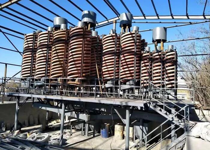
This article explains the key inspection points, commissioning procedures, and acceptance requirements for FRP spiral chute systems.
1. Check Equipment Documentation Before Starting Installation
Before installing an FRP spiral chute, verify the equipment documentation and confirm that the actual components match the approved project requirements.
The inspection should include:
- Equipment model and identification information.
- Spiral chute sections and component markings.
- Support frames and structural components.
- Delivery list and equipment configuration.
- Assembly drawings and installation instructions.
- Foundation or platform interface drawings.
- Manufacturer’s operation and maintenance manual.
- Project specifications, contract requirements, and manufacturer-approved technical records.
Inspect the Spiral Chute Surface and Components
Before assembly, inspect the FRP spiral chute sections for:
- Transportation damage.
- Cracks or visible surface defects.
- Local deformation.
- Damage to the working surface.
- Abnormalities around connection areas.
Record the location and condition of any defects and request the manufacturer’s recommended corrective action.
Do not independently grind, fill, or modify the working surface before obtaining technical approval. Even localized surface changes may affect slurry flow characteristics.
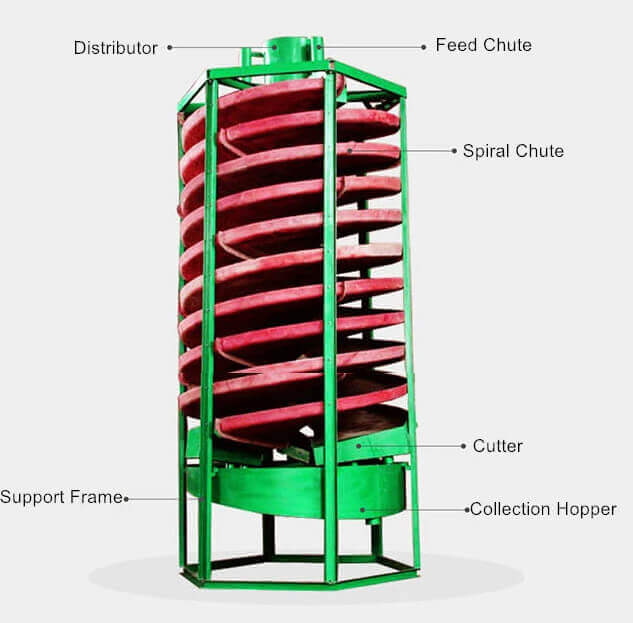
2. Inspect Spiral Chute Alignment, Connections, and Support Structures
After confirming the equipment components, inspect the installation of the spiral chute body and its supporting structure.
For multiple spiral chute units installed on a common support frame or platform, the overall arrangement should be checked against the approved equipment layout.
Important inspection points include:
- Correct installation sequence of spiral chute sections.
- Correct spiral direction and orientation.
- Proper connection between adjacent chute sections.
- Secure installation of support frames.
- Correct positioning of the complete equipment assembly.
- Connection integrity and fastening conditions.
- Condition of protective and safety facilities.
Check Chute Connections and Joint Conditions
The connection between adjacent spiral chute sections is particularly important.
Inspect each joint for abnormal misalignment, visible damage, or signs of leakage that could interfere with slurry movement.
Installation tolerances, measurement reference points, and acceptable joint conditions must be determined by the specific manufacturer’s documentation and approved project requirements.
If abnormal conditions are identified, record them and confirm the repair method before proceeding with commissioning.
Important: There is no universal installation tolerance that applies to every FRP spiral chute model. Always use the technical requirements applicable to the actual equipment.
3. Inspect the Ore Distribution System and Every Feed Inlet
The ore distribution system is one of the most important parts of spiral chute installation acceptance.
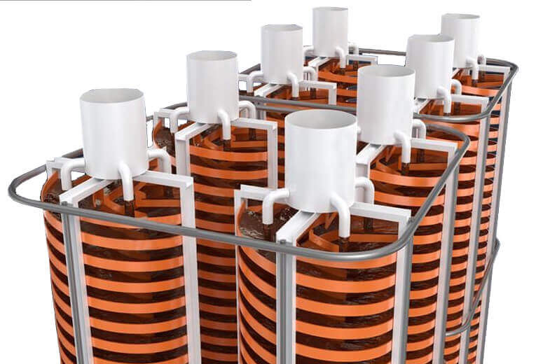
In a multi-unit spiral chute system, slurry usually enters a common distribution box or manifold before being divided among individual spiral chute inlets.
Even when the main feed pipe supplies a stable slurry flow, individual branches may experience different feed conditions.
Potential problems include:
- Uneven slurry distribution.
- Blocked feed branches.
- Unstable flow in individual inlets.
- Air entrainment.
- Differences in feed concentration or dry-solids throughput.
- Incorrectly positioned connecting pipes.
Check Every Feed Branch Separately
Inspection should cover the complete feed distribution path, including:
- The main slurry distribution box.
- Connecting pipes between the distributor and individual units.
- Branch pipes and feed inlets.
- Pipe supports and fixing points.
- The slurry flow condition at each inlet.
Each feed branch should be numbered and inspected separately.
Do not inspect only the easiest-to-access inlet and assume that all other branches have the same operating conditions.
Compare Feed Distribution Under Consistent Conditions
Where feed distribution measurements or sampling are required, use consistent sampling methods and comparable operating conditions.
Record:
- Sampling location.
- Sampling time.
- Feed flow conditions.
- Slurry concentration.
- Dry-solids throughput, where measured.
- Observed differences between individual branches.
The acceptable variation between feed branches should be established according to the manufacturer’s specifications and project acceptance criteria.
A stable main feed does not automatically guarantee uniform feed distribution across all spiral chute units.
4. Conduct a Water Test, but Do Not Treat It as Final Acceptance
A water test is an important step in FRP spiral chute commissioning. However, it cannot replace an actual ore-slurry test.
The two tests have different purposes.
Water Testing: Verify Basic Flow Conditions
During the water test, inspect:
- Whether the flow path is unobstructed.
- Whether water moves smoothly through the chute.
- Whether connection points show signs of leakage.
- Whether the distributor supplies the intended flow paths.
- Whether the discharge and collection systems receive the water properly.
If abnormal flow is observed, inspect the chute surface, joints, and external connecting pipes.
Do not attempt to compensate for an upstream installation problem simply by changing the position of the downstream product splitter.
Ore-Slurry Testing: Verify Actual Operating Performance
After the water test is completed, conduct an ore-slurry commissioning test under the agreed test conditions.
The test should consider:
- Representative ore samples.
- Feed particle-size distribution.
- Slurry concentration.
- Feed rate and operating load.
- Feed distribution conditions.
- Product collection performance.
Observe the slurry distribution along the spiral chute and collect representative product samples for analysis.
This helps distinguish between problems caused by upstream feed fluctuations, uneven distribution, and abnormalities in the chute body.
A clear mineral flow pattern during a short test does not necessarily demonstrate that the equipment can achieve its expected separation performance under design operating conditions.
5. Inspect the Product Splitter and Concentrate Collection System
The inspection does not end when the slurry reaches the bottom of the spiral chute.
The product splitter and downstream collection system must also be checked because they determine whether separated mineral products can be collected independently.
According to the equipment manufacturer’s documentation, inspect:
- Product splitter installation position.
- Splitter fixing and adjustment arrangements.
- Approved adjustment range.
- Concentrate discharge path.
- Middlings discharge path.
- Tailings discharge path.
- Collection tank positioning and capacity.
- Downstream conveying and handling connections.
Prevent Product Mixing After Separation
Even if mineral particles have been separated along the spiral chute, incorrect discharge connections may cause the products to mix again.
Common problems include:
- Incorrect outlet connections.
- Leakage between collection compartments.
- Insufficient collection tank capacity.
- Cross-contamination between concentrate, middlings, and tailings.
- Inadequate downstream material handling capacity.
Therefore, the concentrate, middlings, and tailings should be collected separately and checked individually during commissioning.
Evaluate Splitter Adjustments Through Test Results
When adjusting the product splitter, record each adjustment and compare the resulting product characteristics under stable operating conditions.
Relevant evaluation indicators may include:
- Qualité du concentré.
- Product yield.
- Recovery rate, where calculated.
- Tailings grade and valuable mineral losses.
- Middlings characteristics.
The treatment or recycling route for middlings should be defined in the approved test plan.
Middlings should not automatically be returned to the raw feed system without evaluating their composition and the intended process flowsheet.
6. Establish a Clear FRP Spiral Chute Installation Acceptance Sequence
A reliable acceptance process should distinguish between installation inspection, water testing, and actual ore-slurry performance verification.
These are separate stages and should not be combined into a single acceptance statement.
Stage 1: Installation Inspection
Confirm that:
- Equipment models match the approved documentation.
- Components are complete and correctly assembled.
- The chute body and support structure are properly installed.
- Connections and joints meet applicable requirements.
- The ore distribution system is correctly installed.
- The product splitter and collection system are properly connected.
Stage 2: Water Test
Confirm that:
- Water flow paths are unobstructed.
- No unacceptable leakage is observed.
- Individual feed branches are checked.
- The discharge system functions as intended.
- Collection tanks can receive the discharged water.
Stage 3: Ore-Slurry Commissioning
Under agreed test conditions, verify:
- Actual slurry distribution.
- Feed stability.
- Mineral flow conditions.
- Separate collection of concentrate, middlings, and tailings.
- Product quality and separation indicators.
Stage 4: Documentation and Final Acceptance
Prepare the relevant inspection and commissioning records, including:
- Equipment inspection records.
- Installation photographs.
- Chute alignment and connection inspection records.
- Feed distribution inspection results.
- Water test records.
- Ore-slurry commissioning results.
- Outstanding issues and corrective actions.
- Reinspection and approval records.
The responsible parties should confirm the results according to the project acceptance procedure.
7. Conclusion: Inspect the Entire Spiral Chute System, Not Just the Chute Body
FRP spiral chute installation acceptance requires more than confirming that the equipment is standing securely and that water can flow through it.
The chute body, ore distribution system, product splitter, and downstream collection equipment work together as one separation system. A problem in any of these areas may affect actual mineral processing performance.
A reliable acceptance process should follow three essential principles:
- Inspect the installation: Verify the chute body, support structure, connections, and component arrangement against approved technical documentation.
- Verify feed distribution: Check every feed branch rather than relying on the condition of the main slurry pipeline.
- Confirm product collection and performance: Conduct water testing and ore-slurry commissioning separately, then evaluate the collected products.
Most importantly, installation acceptance, water-test approval, and ore-slurry performance verification should be recorded as separate results.
A properly installed spiral chute is only the starting point. Complete acceptance means verifying the entire process from slurry distribution to final product collection.
DERNIERS PRODUITS
-

Handheld Rock Drills
【Drilling Hole Diameter】30-45 mm 【Dill Hole De…
-
Hydraulic Rock Drills
【Drive Method】 Driven by high-pressure hyd…
-
Gasoline Rock Drills
【Engine Type】 Gasoline engine …


 English
 French
 Spanish
 Portuguese
 Indonesian