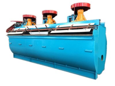
Flotation Cells & Machines

Introduction

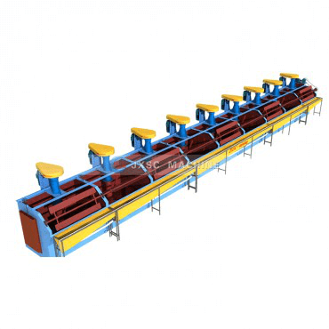
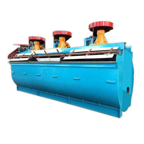
Flotation machines constitute the basic equipment for useful minerals recovery from non-ferrous ores and other raw materials by flotation. They can operate also as individual flotation cells.


Flotation Cells (Froth Flotation) were developed to separate and recover high-value Sulphide ores from low-grade ore bodies. The Flotation Cell is aerated to produce bubbles and agitated to keep the solids particles in suspension in the pulp. A flotation cell is an appliance in which froth flotation of ores is performed. It has provision for receiving conditioned pulp, aerating this pulp, and for separate discharge of the resulting mineralized froth and impoverished tailings.

flotation machine

Our Flotation Machines/Cells

Ask for flotation machines & cells?

Types of Flotation Machines


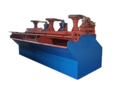
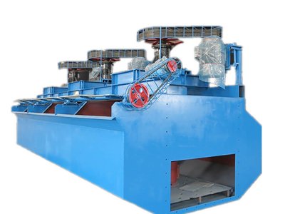
JXSC Machinery Factory is a professional R & D and production manufacturer of flotation cells/machines. Our froth flotation separation is sold all around the world and is popular with clients. The types of our flotation cells are main including SF, XJK, JJF, XCF, KYF flotation cells.

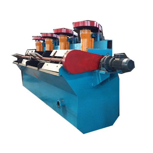
SF flotation cell is a mechanical agitation type with slurry suction and air suction.

Capacity: 0.24~12m³/min

Structure
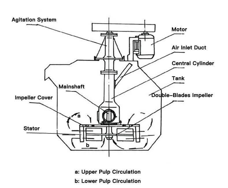
The structure of the SF flotation cell is mainly composed of the tank, impeller, motor, scraper and transmission device, etc.

sf flotation machine structure


Features

  • It can be combined with the JJF flotation cell in a combined flotation unit as a sucking tank for every operation.
  • Mechanical agitation with self-air-inflation and self-priming pulp.
  • Upper and lower recirculation in the well-defined path, sanding of coarse particles is minimized, it is advantageous for coarse ore flotation.
  • The gap between the impeller and cover plate is large with a large air inflation amount. Less energy consumption.
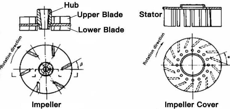
  • Backward double-sided blades are equipped on the impeller, which realizes the double loop of slurry in the tank.
  • Lower speed of the rotor to extend wear life.
  • Forward leaning tank with small blind angle. The foam moves fast. Beveled tank design, stable operation, and proven metallurgical design.

Working Principle

When the rotor is rotating, an internal vacuum is created both in the upper and lower blade zone. Ambient air is drawn through an air intake pipe and standpipe by the action of the upper blade, the bubbles are then micronized and make the minerals easier to stick on the bubbles. Mineral particles are collected by air bubbles forming aggregates in the contact zone, and Mineralized Bubbles aggregates rise by buoyancy towards the froth zone. The pulp from the upper tank zone is recirculated by the upper blade, while the lower blade is designed to recirculate slurry from the bottom of the tank to minimize the sanding of coarse particles.

sf flotation cell working principle


Technical Parameters

ModelVolume(m3Cell Size(mm)Impeller Dia.(mm)Impeller Speed(r/min)Capacity(m3/min)Power(kW)Singe cell weight(kg)
SF-0.370.37700×700×7502963860.2-0.41.5/0.55468
SF-0.70.7820×900×9503504000.3-0.93/1.1 805
SF-1.21.21100×1100×11004503120.6-1.25.5/1.11373
SF-2.82.81700×1600×11505502681.5-3.511/1.52138
SF-441850×2050×12006502202–415/1.52582
SF-882200×2900×14007601914–830/1.54129
SF-10102200×2900×17007601915–1030/1.54486
SF-16162850×3800×17007601915–1630×2/1.58320
SF-20202850×3800×20007601915–2030×2/1.59829


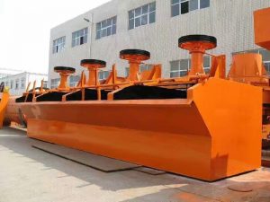
XJK flotation machine suitable for separation of non-ferrous metals, ferrous metals, precious metals,non-metallic mineral, and chemical raw materials, recovering useful minerals.

Capacity: 0.18~7m³/min

xjk flotation machine

Features

  • Large inhaling capacity and low energy consumption.
  • Complete flotation circuit with inhaling air and pulp, no auxiliaries are needed.
  • The process is easy to be changed.
  • Reasonable circulation of pulp decreases coarse sand sedimentation.
  • Automatic controlling device makes adjustment more convenient.

Working Principle

The mineral pulp being added pharmacy will be passed into the gas, and the electric rotor will bring the movement of part pieces to mix and stir in order to make the mineral and gas be sufficiently mixed, and at this minute, the grain of mineral pulp is above on the bubble, floating on the surface, which can reach the purpose of sorting the mineral material through blade scrapings.

Technical Parameters

ModelVolume(m3Cell size(mm)Impeller Dia.(mm)Impeller speed(r/min)Capacity(m3/min)Power for Stir/Scraper(kw)Singe cell weight(kg)
XJK-3A0.35700×700×7003004830.18-0.42.2/0.55430
XJK-4A0.62820×900×8503504000.3-0.93/1.1755
XJK-5A1.11100×1100×10005003300.6-1.65.5/1.11416
XJK-6A2.81750×1600×11006002801.5-3.511/1.12113
XJK-7A5.82200×2200×12007502403–722/1.53400


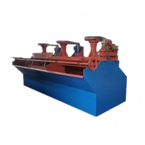
JJF flotation machine is an air self-suction mechanical stirring floatation cell without slurry suction

Capacity: 2~20m³/min

jjf flotation machine

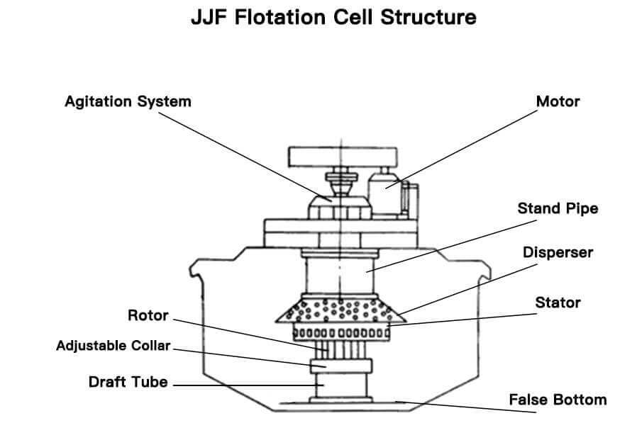
Structure

jjf flotation cell structure

Features

  • Low power consumption due to small diameter and low speed of the rotor.
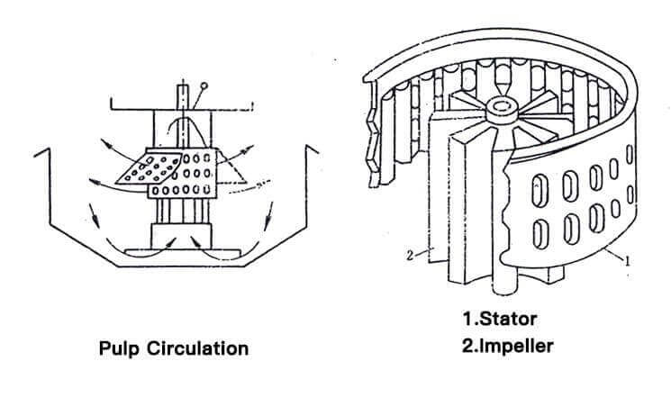
  • Large design clearance between the rotor and disperser resulting in minimal wear. The stator is a cylinder with an oval hole, which is conducive to the mixture and dispersion of air and pulp.
  • The height of the stator is rather lower than the impellers. The pulp circulation amount is large(up to 2.5 times), which is conducive to the mineralization of ore, reagent and air, also good circulating of pulp and mixing of pulp with air.
  • The umbrella-shaped perforated dispersion cover of the stator can block off the foam layer from the vortex by the impeller, to keep the stabilization of the pulp surface.
  • Large air inflation amount, good dispersion effect.
  • Shorter froth travel distance for improved coarse particle recovery.
  • A beveled tank bottom for coarse particle suspension.
  • Large processible granularity range and high recovery rate.
  • The rotor is well above the tank bottom, eliminating contact with abrasive, oversized tramp material.
  • Mechanical agitation. Self-air-inflation without self-priming pulp.
  • It can be combined with SF flotation cell in combined flotation unit, with SF flotation cell as a slurry suction tank and JJF flotation cell as the straight tank.

Working Principle

When the JJF mechanical agitation flotation machine is working, the rotor creates a fluid vortex inside the standpipe and the draft tube, and causes a sufficient vacuum area to induce air into the standpipe through the air inlet duct. The induced air is mixed with pulp between the impeller and stator. The mixture of air and pulp will have a tangential movement as a result of the impeller. But when the Mineralized Bubbles pass through the pores on the stator, they change to a radial motion until they bump into the Disperser and be separated evenly. When the Mineralized Bubbles rise up to the froth zone, the scraper revolves to discharge the products.

jjf flotation cell working principle

Technical Parameters

ModelVolume(m3Cell size(mm)Impeller Dia.(mm)Impeller speed(r/min)Capacity(m3/min)Power for Stir/Scraper(kw)Singe cell weight(kg)
JJF-111100*1100*1000280 0.3-15.5/1.5 
JJF-221400*1400*1150280 0.5-27.5/1.5 
JJF-331500*1850*1200350 1-311/1.5 
JJF-451600*2150*12504103052.0-411/1.52303
JJF-551600*2150*15504103052.0-611/1.52416
JJF-882200*2900*14005402334.0-1222/2.24507
JJF-10102200*2900*17005402335.0-1022/1.54820
JJF-16162850*3800*17007001805.0-1637/1.57657
JJF-20202850*3800*20007701805.0-2045/1.58505


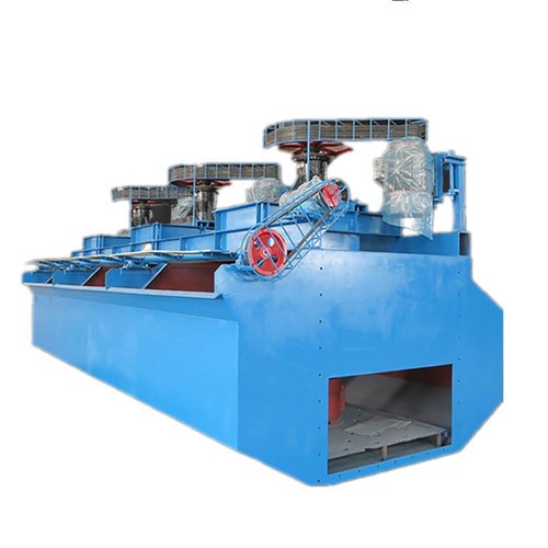
XCF flotation machine is an air inflation mechanical agitation flotation cell with slurry suction. 

KYF flotation machine is an air-inflation mechanical agitation flotation cell without slurry suction.

Capacity: 0.2~38m³/min

xyf/kyf flotation machine

Structure

XCF/KYF flotation machine is composed of a tank, large isolation plate impeller with top and bottom blades, seat stator radial blade, split disc cover, split center tube, connecting tube with air-bleed hole, bearing body, hollow main shaft, and the air adjustable valve.

Features

  • Simple structure and strong stirring capacity.
  • The air is evenly dispersed. Air and slurry combination is fine.
  • Fewer tailings deposits, low peripheral speed, and low energy consumption.
  • Light wear of quick-wear part with a long working life.
  • Mechanical agitation, without self-air-inflation and self-priming pulp. The ladder configuration between the workroom is essential.
  • The structure features of XCF flotation cell are similar with KYF flotation cell. The difference is that a stator is specially provided above the impeller to form a special negative pressure zone, self-priming pulp.
  • KYF and XCE flotation cells can be combined use.

Working Principle

When the flotation machine is at work, the rotation of impeller makes the slurry all-around via tank bottom absorbed from the downside of impelled into inner-vanes of the impeller, where low-pressure air is produced by the blower goes into via hollow shaft and the air distributor of impeller chamber at the same time. After a full mixture of the slurry and air among vanes, they are pushed out in the inclined upward direction from the upper half of the impeller around, and go into the tank via steady f\ow and orientation by the stator. Air bubbles rise to the foam stability area, and after the concentration process, the froths overflow from the overflow weir into the froth tank. Another part of the slurry flows toward the lower part of the impeller, then through the impeller agitation, they are mixed together to form mineral-laden bubbles again, and the rest of the slurry will flow to the next tank to become tailings eventually.


ModelVolume
 (m3)
Capacity
 (m3/min)
Impeller
 Diameter
 (mm)
Impeller
 Speed
 (r/min)
Power(kW)Singe Cell Weight
 (kg)
     For StirringFor Scraper 
XCF-110.2 -14003585.51.11154
XCF-220.4 -24703317.5 1659
XCF-330.6 -3540266111.52259
XCF-441.2 -462021515 2669
XCF-883.0 -872018522 3958
XCF-16164-1686016037 6520
XCF-20205-1091015545 9200
XCF-24244-2495015355 9660
XCF-30307-15100014155 14810
XCF-383810 -38105013655 17000
XCF-404010-38105013875 17500
XCF-505010-25112011090 22000
XCF-707013-50120010390 26200


ModelVolume
 (m3)
Capacity
 (m3/min)
Impeller
 Diameter
 (mm)
Impeller
 Speed
 (r/min)
Power(kW)Singe Cell Weight
 (kg)
For StirringFor Scraper
KYF-110.2-134028141.1826
KYF-220.4-24102475.51419
KYF-330.6-34802197.51.51885
KYF-441.2-4550200112206
KYF-883.0-8630175153600
KYF-16164.0-16740160305900
KYF-20205-20780155378240
KYF-24244.0-24800150378540
KYF-30307-309001414513820
KYF-383810-388801394516500
KYF-404010-389501385517000
KYF-505010-4010301207522000
KYF-707013-5011201109026200


Inquiry Now