If you’re in the market for a belt scale, JXSC will teach you everything you need to know about installation. By the end of this article, you’ll know how to install a belt scale correctly and safely. Keep reading to learn more!
Installation of Belt Scales
How to Install Belt Scale Frame?
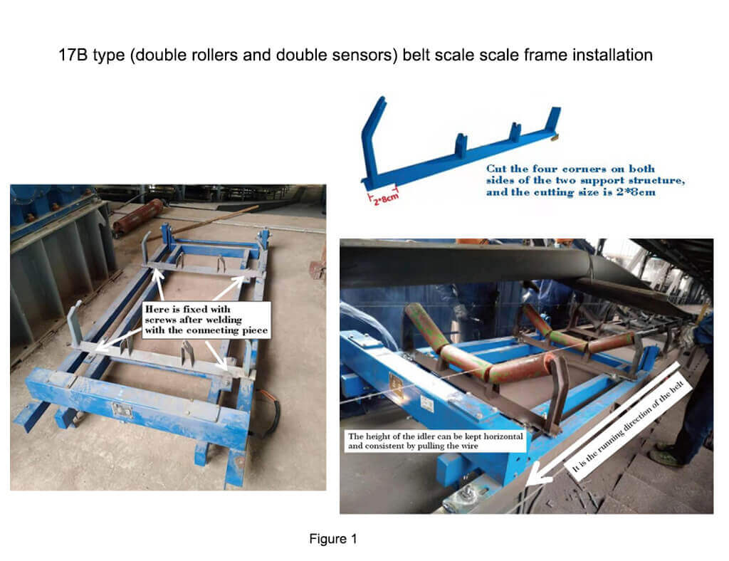
● 17B Type (double rollers and double sensors) Belt Scale Scale Frame Installation
The installation of this scale frame needs to pay attention to the installation direction of its scale frame, the trunnion’s one side towards the end of the belt conveyor, and the sensor beam towards the belt’s running direction. After dismantling the corresponding two sets of idler brackets, the disassembled idler bracket is cut at the bottom of both ends, and the cutting size is 2*8cm. And welded the cut processed idler on the connecting piece of the belt scale, then fixed it on the scale frame of the belt scale with screws. (Shown as figure 1)
Note: The rollers on the scale frame and front-rear rollers on the conveying frame should keep the same height. When the belt is running, the contact between the front-rear rollers of the belt scale and the two rollers on the belt scale and the belt should be close and effective. Consistent, and turn in unison.
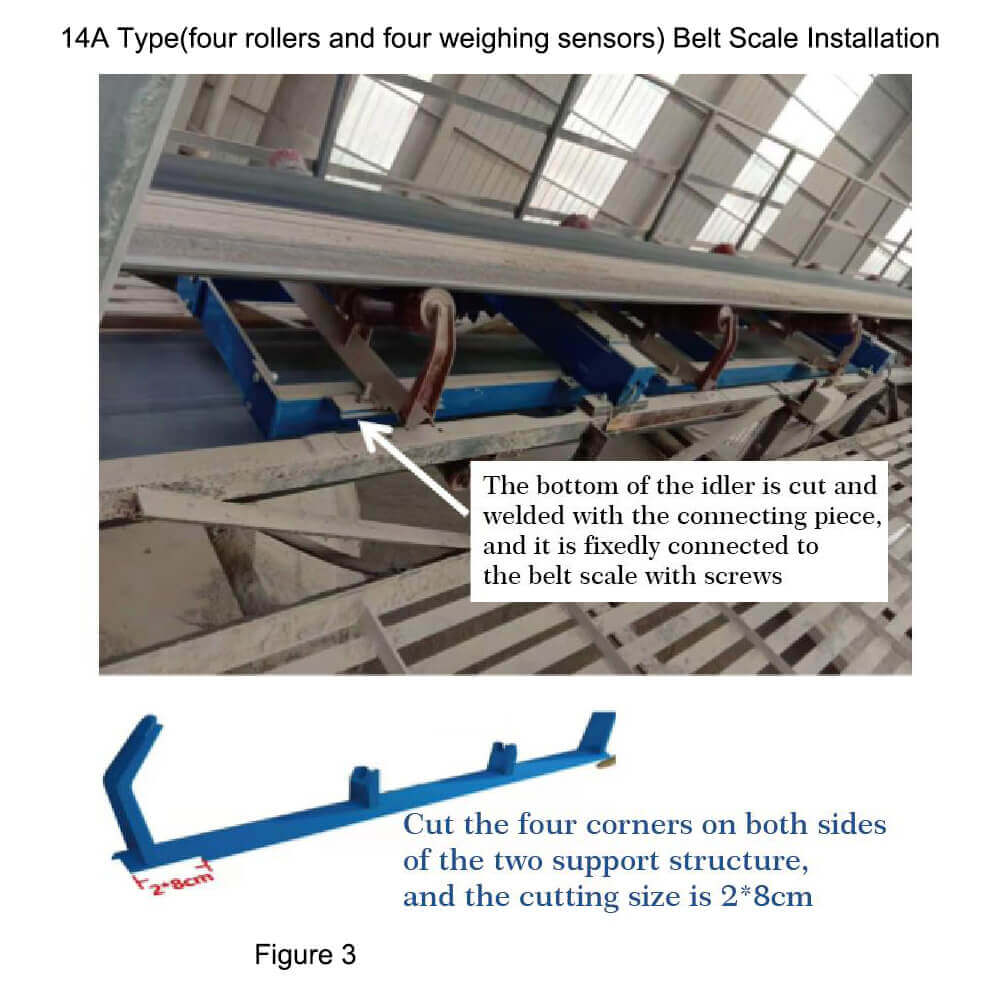
● 14A Type(four rollers and four weighing sensors) Belt Scale Installation
Model 14A (four rollers and four weighing sensors) is installed on a belt scale. The installation of this scale does not need to pay attention to the installation direction of the belt scale. We disassemble the corresponding four sets of idler brackets and cut the ends of the disassembled idler brackets with a cut size of 2*8cm. Solder the cut idler on the connecting piece of the belt scale, then fix it on the scale frame with screws. (Shown as figure 3)
Note: The rollers on the scale frame and the front-rear rollers on the conveying frame should keep the same height. After the belt runs, the contact between the front and rear rollers of the belt scale while the four rollers on the belt scale and the belt should be close and effective. Consistent, and turn in unison.
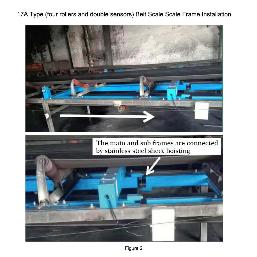
● 17A Type (four rollers and double sensors) Belt Scale Scale Frame Installation
The installation of this scale frame needs to pay attention to the installation direction of the belt scale frame. The main frame of the belt scale has one end of the trunnion facing the tail end of the belt conveyor, the sensor beam facing the belt’s forward direction. The sub-frame and the sensor beam are made of stainless steel—hoisting connecting steel plate. Disassemble the corresponding four sets of idler brackets, and cut the ends of the disassembled idler brackets. The cut size is 2*8cm. Sold the cut idler on the connecting piece of the belt scale, then fixed it on the scale frame with screws. (Shown as figure 2)
Note: The scale frame’s rollers should be the same height as the front and rear rollers on the conveying frame. After the belt is running, the front and rear rollers of the belt scale should be The contact between the four idlers on the belt scale and the belt should be close and effective, the height should be consistent, and the rotation should be constant.
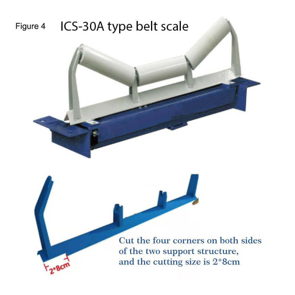
● 30A Type(single idler and double weighing sensors) Belt Scale Scale Frame Installation
The installation of the scale frame does not need to pay attention to the installation direction of its scale frame. We disassemble the corresponding four sets of idler brackets and cut the ends of the disassembled idler brackets. The cut size is 2*8cm. Solder the cut idler on the connecting piece of the belt scale, then fix it on the scale frame with screws.(Shown as figure 4)
How to Install The Weighing Sensor?
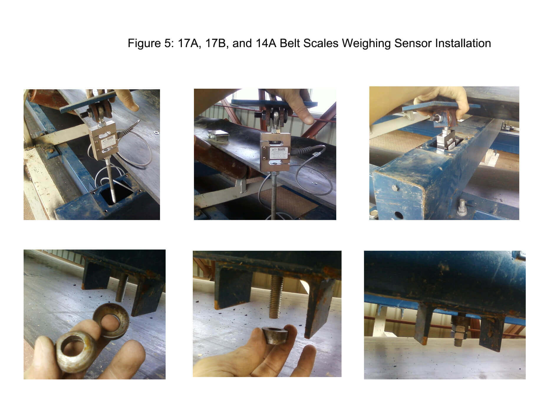
- 17A, 17B, and 14A belt scales
For 17A, 17B, and 14A belt scales, the sensors are installed in the sensor beam. The specific installation is as figure 5. - 30A belt scale
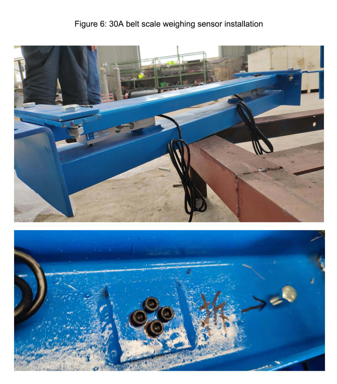
The weighing sensor of the 30A belt scale has been installed at the factory, in order to protect the sensor during delivery, there is a screw at the bottom of the 30A to protect the sensor, which must be removed before debugging and installation. Shown as figure 6.
How to Install The Speed Sensor?
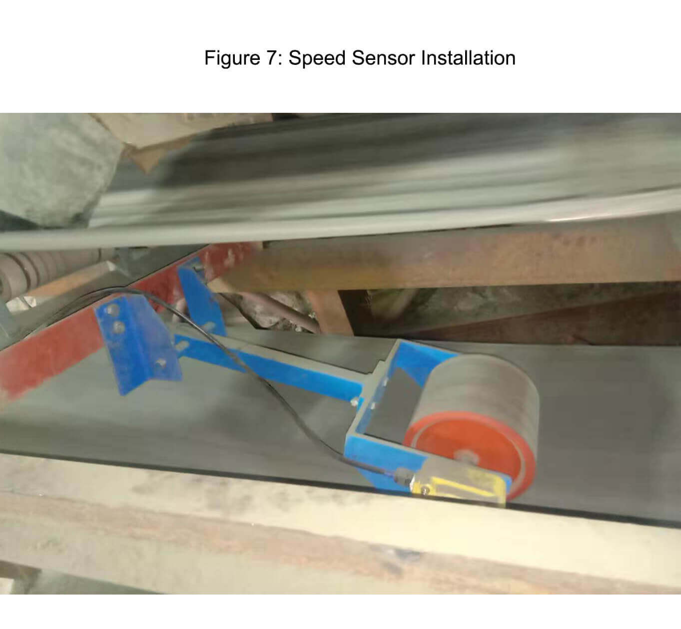
The installation position of the speed sensor is generally installed in a steady place where the belt is relatively stable, with small jumping and floating. The installation method is not limited to the following ways, and it can adjust the installation method according to the site conditions. The purpose is to make the belt rotation to drive the rotation of the tachometer wheel smoothly so that we can measure the speed(Shown as figure 7).
How to Wire The Instrument?
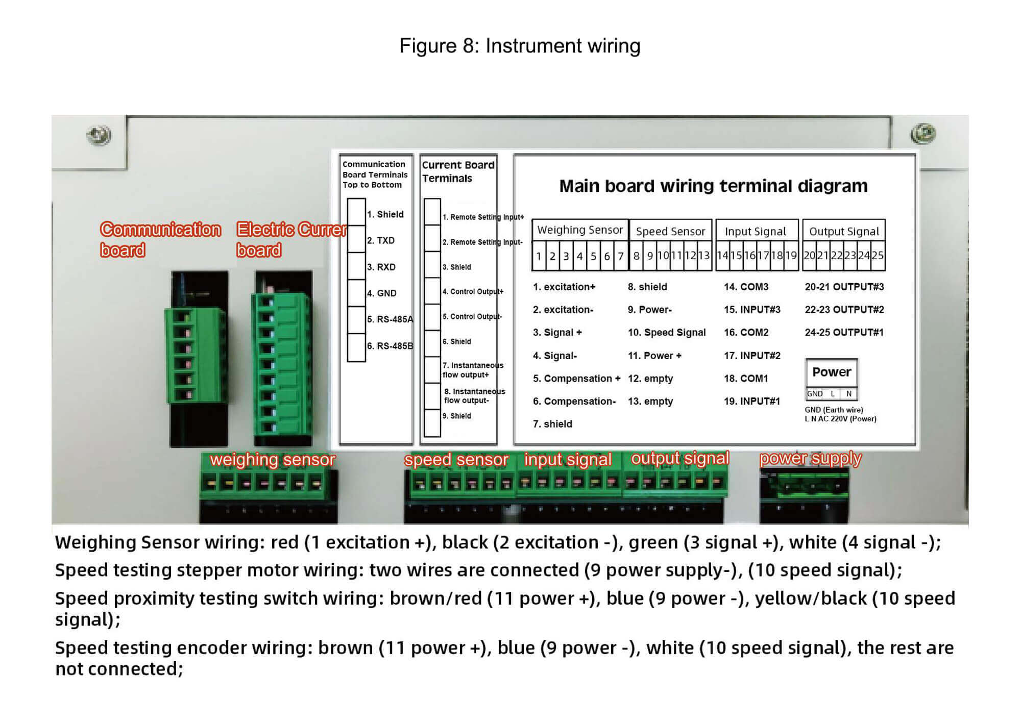
1400 type, 2015 type, 6 series, and other instrument wiring is as follows
All the weighing sensors of a single belt scale can be connected to the junction box in parallel and then lead out the four-core shielded wire from the junction box to the instrument.
The speed sensor in the tachometer wheel will have a different choice according to the various required speeds of the customer. Don’t hesitate to contact the seller to check which speed sensor to use and then connect according to the wiring diagram(Shown as figure 8).
Installing a belt scale is not a difficult task. By following the steps outlined in this article, you can have your belt scale up and running in no time. With a little bit of planning and preparation, you can ensure that your belt scale installation goes smoothly. Further, we will show you the debugging of the belt scale.
LATEST PRODUCTS
Tubular Screw Conveyor
【Capacity】6-50 m3/h【Procesible Material】 …
Heavy Plate Feeder
Capacity: 100-240 m3/h Power: 15-45 kW Speed: 0…
Plate Magnetic Separator
【Capacity】8-35 t/h 【Power】1.5-3 kW 【Applic…


