


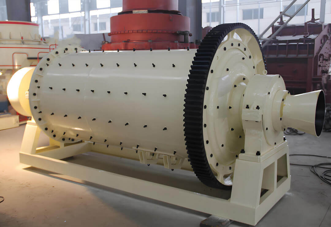
The Ф600×900 ball mill is a key industrial grinding machine designed for crushing and grinding various raw materials into fine powders. Widely used in mining, cement, ceramics, and chemical processing industries, this equipment ensures efficient and reliable operation when correctly installed, maintained, and operated.
This technical manual provides comprehensive guidance on the structure, working principle, installation requirements, testing procedures, operational steps, and maintenance practices for the Ф600×900 ball mill. By following these instructions, operators can maximize equipment lifespan, prevent unexpected failures, and maintain optimal grinding efficiency. Proper adherence to safety protocols is mandatory throughout all operational phases.
Ф600×900 Ball Mill Introduction
The Ф600×900 ball mill is mainly used in industries such as mineral processing, ceramics, chemical engineering, and cement, and is available in dry and wet types. The main component of a ball mill is a slowly rotating cylinder filled with grinding media. Due to its simple and robust structure, reliable operation, easy maintenance and management, ability to run continuously for a long time, strong adaptability to materials, large crushing ratio (up to 300 or more), and high production capacity, it can meet the needs of modern large-scale industrial production.
Performance
| Specification Model | Φ600×900 Ball Mill |
| Feed Particle Size | 0-25mm |
| Discharge Particle Size | 0.074-0.4mm |
| Motor Model | Y132M1-6 4KW |
| Voltage | 230V |
| Frequency | 50Hz |
| Cylinder Rotation Speed | 44r/min |
| Filling Rate | 27% |
| Reducer Model and Gear Ratio | FA77-Y4.0-6P i=11.31 |
Main Structure
The Ф600×900 ball mill features an edge-driven design with central discharge. Its core components include:
- Rotating cylinder
- Feed and discharge mechanisms
- Support roller assemblies
- Reduction gearbox
- Drive motor
Rotating Assembly (Cylinder)
- Constructed from welded steel plates with bolted connections to feed/discharge hollow shafts
- Horizontally mounted on support rollers for stable rotation
- Driven by a motor, a reducer, a pinion gear, and a large ring gear mounted on the cylinder
- Internally lined with rubber for:
1. Cylinder protection
2. Optimal ball lifting to enhance grinding efficiency
Feed & Discharge Systems
- Feed end: Controls material input
- Discharge end:Handles:
1. Processed materials
2. Worn grinding media
3. Hard contaminants
Support Structure
- Dual roller assemblies support the combined weight of:
1. Rotating components
2. Grinding media
3. Process materials - Critical for operational stability
Drive System
Power transmission flows through:
Motor → Reducer → Support Rollers → Tyre Drive
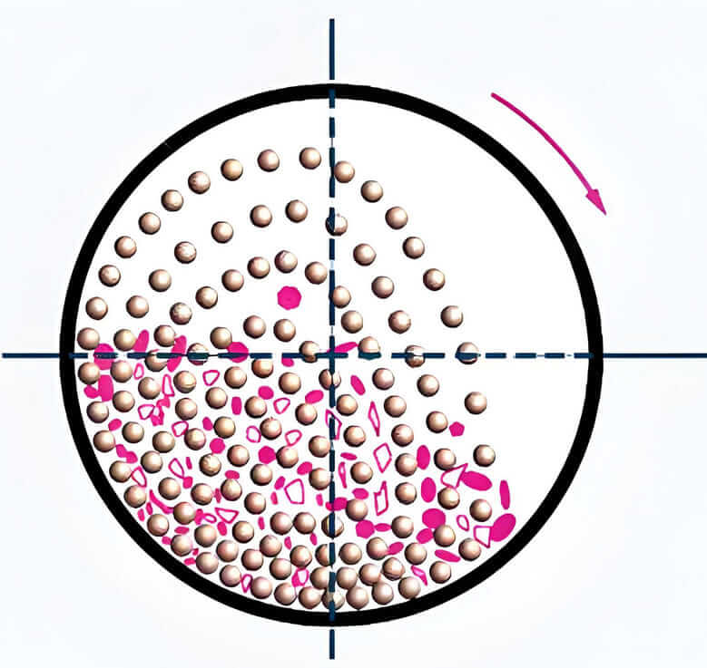
Working Principle
When the motor drives the cylinder to rotate through the reducer, supporting rollers, and tyre, the crushing media (steel balls) installed in the cylinder and the continuously fed materials rise to a certain height with the cylinder under the action of centrifugal force and friction, then break away from the cylinder wall and fall freely. The crushing of materials mainly relies on the impact force when the media falls and the abrasion effect during movement. Materials are continuously fed from the inlet end, and the ground products are continuously discharged from the other end of the cylinder.
What Are The Requirements For The Installation of Ф600×900 Ball Mill?
In addition to complying with all technical specifications in the provided drawings, the ball mill installation must meet the following critical requirements:
Pre-Installation Inspection
Thoroughly examine all key components before assembly, including:
- Cylinder integrity(check for roundness and weld quality)
- Supporting rollers(inspect bearing surfaces and alignment)
- Transmission bearings(verify lubrication and clearance)
- Reducer assembly(confirm no shipping damage exists)
Action Required: Complete all necessary repairs for any detected deformation or damage prior to installation.
Cleaning & Preparation Protocol
- Component Cleaning:
- Degrease and remove contaminants from:
- All mating surfaces
- Bearing journals
- Gear engagement areas
- Degrease and remove contaminants from:
- Pre-Commissioning Verification:
- Recheck the cleanliness of installed components
- Perform secondary cleaning if visual inspection reveals:
- Metal particles (≥0.5mm)
- Residual grease exceeding manufacturer specs
Foundation Installation Procedure
- Positioning:
- Establish centerline reference using laser alignment tools
- Mark base plate positions per drawing dimensions (±2mm tolerance)
- Alignment & Fixation:
- Adjust base elevation with precision shims (gradation 0.05mm)
- Final welding to embedded parts must:
- Follow the approved weld sequence
- Incorporate thermal distortion control measures
- Meet AWS D1.1 structural welding standards
Critical Installation Notes:
- Maintain ambient temperature >5°C during base welding
- Verify perpendicularity between the cylinder axis and support roller planes (≤0.1mm/m)
- Document all alignment measurements for quality records
How to Test, Operate, and Maintain a Ф600×900 Ball Mill?
Test Run
After the ball mill is installed and meets the installation requirements, the test run can be carried out. The test run procedure is as follows:
- Fill the reducer with lubricating oil as required, and add gear oil to the gear.
- Run the ball mill idly for 24 hours (without grinding media).
- Add1/3 of the grinding media and feed materials, running for 8.
- Add2/3 of the grinding media and feed materials, running for 72.
During the test run, pay attention to the temperature of the rotating parts. The temperature of the transmission bearings shall not exceed 70℃. During the test run of the reducer, closely monitor the oil supply condition of each lubrication point, whether the load of the motor and the sound of the reducer are abnormal, and strictly note the vibration condition in each test run. After shutdown, check the tightness of anchor bolts, liner fastening bolts, etc.
Formal Operation
After the test run is qualified, formal operation is allowed. Users can formulate operation, maintenance, and repair systems according to specific conditions to ensure the normal operation of the equipment.
Knowledge of Ball Mill Operation
There are two common methods to determine whether the ball mill is running normally:
- The first method is to check the discharge particle size. If it meets the requirements and the fluctuation is small, it indicates that the ball mill is running normally, meaning the feeding is appropriate, the feed particle size and moisture are suitable, and the steel ball gradation is
- The second method is to listen to the sound of the ball mill. When the equipment is running normally, it should make a “whooshing” sound with a slight impact. If the sound becomes dull and makes a “roaring” sound without impact sounds, it indicates that there is too much material in the bin, and severe full-mill phenomenon may occur. At this time, feeding should be stopped immediately, and feeding can be continued after the equipment returns to normal operation. If the normal sound still cannot be heard after stopping feeding, the material is difficult to feed, and the discharge is very little, for a dry ball mill, it indicates severe sticking in the cylinder, which should be handled immediately. Generally, the following methods can be used to solve it: if the moisture of the feed material is too high, the moisture of the feed material should be reduced to within 2%, or part of dry material can be added, and grinding can eliminate the above phenomenon. This phenomenon will not occur in a wet ball mill.
If the impact sound of the steel balls is very strong, it indicates that there is less material in the cylinder, and the feeding should be increased. The feeding amount should not be too strong and should be adjusted gradually.
Operation Procedure of Ball Mill
Preparations Before Startup
- Removes sundries around the ball mill that may hinder operation, and checks safety
- Check whether there are people inside the ball mill and in a dangerous area
- Check whether the lubrication points and lubricating oil are
- Before starting the ball mill, also contact the relevant work posts and start after
Startup Sequence of Ball Mill
- Start the discharge conveying
- Start the ball mill
- Start the feeding device of the
Shutdown Sequence
- Stop the feeding equipment for feeding the ball
- Stop the operation of the ball
- Close the discharge conveying
Precautions
- When the ball mill is prepared to stop running for a long time, the grinding media should be taken out of the cylinder to avoid the cylinder bending.
- Regularly check the lubrication condition of the
Maintenance of Ball Mill
- Regularly check whether important bolts, such as anchor bolts and liner bolts, are loose.
- Check the lubrication condition of each lubrication point at least once every hour. The temperature of the transmission bearings is not allowed to exceed 70℃, and the temperature of the reducer is not allowed to exceed 55℃.
- Check whether there is water leakage, oil leakage, material leakage, etc., at each seal.
- Record the change in the motor current. If any abnormal change in the current is found, stop the machine for inspection.
- In order to detect potential equipment failures promptly, in addition to normal maintenance, the machine must be shut down regularly to carefully check the connection and wear conditions of important components, make correct handling of the found defects, and make detailed inspection and repair records.
- The lubricating oil used for the equipment should be selected according to the climate and lubrication points, as shown in the following table:
| Serial Number | Lubrication Position | Lubricating Oil Grade | Climate Condition | Remarks |
| 1 | Bearings | 2# Lithium-based Grease | Winter | |
| 2 | Reducer | Gear Oil N220 | Winter | |
| 3 | Bearings | 2# Lithium-based Grease | Summer | |
| 4 | Reducer | Gear Oil N320 | Summer |
Liner Parts List
| Serial Number | Name | Material |
| 1 | Cylinder Liner | Cast Steel |
| 2 | Grinding Head Liner | Cast Steel |
Conclusion
Proper handling of the Ф600×900 Ball Mill ensures smooth production processes, high grinding efficiency, and minimized downtime. This manual has detailed the structural components, working mechanisms, precise installation steps, safety testing methods, daily operation guidelines, and preventive maintenance strategies to keep the equipment running in optimal condition.
Regular inspections, lubrication, and timely replacements of wear-prone parts are essential for sustaining long-term performance. Should any operational discrepancies or failures occur, consult the troubleshooting section or contact technical support immediately. By following these best practices, operators can enhance productivity, reduce maintenance costs, and ensure workplace safety.
For further technical assistance, refer to the manufacturer’s official documentation or contact certified service personnel.
LATEST PRODUCTS
-

SFM-8 Lab Grinder
【Max. Power Consumption】 150W 【Morta…
-
Cyclosizer
【Feeding Capacity】< 100g/time 【Feeding …
-
JKZ/2JKZ Mine Shaft Sinking Hoist
【Power Source】Electric Motor Drive 【Motor Spee…


